Logic Design
References
- Slides adapted from CMU
Outline
- Introduction to binary logic gates
- Truth table construction
- Logic functions and their simplifications
- Laws of binary logic
Overview of Logic Design
- Fundamental Hardware Requirements
- Communication (how to get values from one place to another)
- Computation
- Storage
- Bits
- Everything expressed in terms of values 0 and 1
- Communication: low or high voltage on wire
- Computation: compute with Boolean functions
- Storage: store bits of information
Digital Signals
- Use voltage thresholds to extract discrete values from continuous signal.
- Simplest version: 1-bit signal
- Either high range (1) or low range (0)
- With guard range between them
- Not strongly affected by noise or low quality circuit elements
- Can make circuits simple, small and fast
Semiconductors to Computers
- Increasing levels of complexity
- Transistors built from semiconductors
- Logic gates built from transistors
- Logic functions built from gates
- Flip-flops built from logic
- Counters and sequencers from flip-flops
- Microprocessors from sequencers
- Computers from microprocessors
Semiconductors to Computers
- Increasing levels of Abstraction
- Physics
- Transistors
- Gates (this lecture)
- Logic (this lecture)
- Microprogramming
- Assembler
- Programming languages
- Applications
Logic Gates
- Basic logic circuits with one or more inputs and one output are called gates
- Gates are used as the building blocks in the design of more complex digital logic circuits.
Representing Logic Functions
- There are several ways of representing logic functions:
- Symbols to represent the gates
- Truth tables
- Boolean algebra
NOT Gate
Truth table
a y 0 1 1 0 Boolean algebra
\[y = \overline{a}\]
AND Gate
Truth table
a b y 0 0 0 0 1 0 1 0 0 1 1 1 Boolean algebra
\[y = a \cdot b\]
OR Gate
Truth table
a b y 0 0 0 0 1 1 1 0 1 1 1 1 Boolean algebra
\[y = a + b\]
XOR Gate
Truth table
a b y 0 0 0 0 1 1 1 0 1 1 1 0 Boolean algebra
\[y = a \oplus b\]
NOT AND (NAND) Gate
Truth table
a b y 0 0 1 0 1 1 1 0 1 1 1 0 Boolean algebra
\[y = \overline{a \cdot b}\]
NOT OR (NOR) Gate
Truth table
a b y 0 0 1 0 1 0 1 0 0 1 1 0 Boolean algebra
\[y = \overline{a + b}\]
Boolean Algebra
Boolean algebra can be used to design combinational logic circuits
- OR
- \(a + 0 = a\)
- \(a + a = a\)
- \(a + 1 = 1\)
- \(a + \overline{a} = 1\)
- AND
- \(a \cdot 0 = 0\)
- \(a \cdot a = a\)
- \(a \cdot 1 = a\)
- \(a \cdot \overline{a} = 0\)
Boolean Algebra Properties
- Commutation
- \(a + b = b + a\)
- \(a \cdot b = b \cdot a\)
- Association
- \((a + b) + c = a + (b + c)\)
- \((a \cdot b) \cdot c = a \cdot (b \cdot c)\)
- Distribution
- \(a \cdot (b + c) = (a \cdot b) + (a \cdot c)\)
- \(a + (b \cdot c) = (a+b) \cdot (a+c)\)
- Absorption
- \(a + (a \cdot c) = a\)
- \(a \cdot (a+c) = a\)
Boolean Algebra Example
Simplify
\[ \begin{align*} & x \cdot y + \overline{y} \cdot z + x \cdot z + x \cdot y \cdot z \\ & x \cdot y \cdot z + x \cdot y \cdot \overline{z} + x \cdot \overline{y} \cdot z + \overline{x} \cdot \overline{y} \cdot z + x \cdot y \cdot z + x \cdot \overline{y} \cdot z + x \cdot y \cdot z \\ & x \cdot y \cdot z + x \cdot y \cdot \overline{z} + x \cdot \overline{y} \cdot z + \overline{x} \cdot \overline{y} \cdot z \\ & x \cdot y \cdot (z + \overline{z}) + \overline{y} \cdot z \cdot (x + \overline{x}) \\ & x \cdot y \cdot 1 + \overline{y} \cdot z \cdot 1\\ & x \cdot y + \overline{y} \cdot z \end{align*} \]
DeMorgan’s Theorem
- \(\overline{a + b + c + \ldots} = \overline{a} \cdot \overline{b} \cdot \overline{c} \cdot \ldots\)
- \(\overline{a \cdot b \cdot c \cdot \ldots} = \overline{a} + \overline{b} + \overline{c} + \ldots\)
Proof for \(\overline{a + b} = \overline{a} \cdot \overline{b}\)
\(a\) \(b\) \(\overline{a + b}\) \(\overline{a} \cdot \overline{b}\) 0 0 1 1 0 1 0 0 1 0 0 0 1 1 0 0
DeMorgan’s Example
Simplify
\[ \begin{align*} & a \cdot \overline{b} + a \cdot (\overline{b + c}) + b \cdot (\overline{b + c})\\ & a \cdot \overline{b} + a \cdot \overline{b} \cdot \overline{c} + b \cdot \overline{b} \cdot \overline{c}\\ & a \cdot \overline{b} + a \cdot \overline{b} \cdot \overline{c}\\ & a \cdot \overline{b} \end{align*} \]
DeMorgan’s in Gates
- The function \(f = a \cdot b + c \cdot d\) can be implemented with AND and OR gates
DeMorgan’s in Gates
- Two consecutive NOT gates cancel out.
DeMorgan’s in Gates
- The function \(f = a \cdot b + c \cdot d\) can be simplified to use only NAND gates.
Logic Minimisation
- Any Boolean function can be implemented directly using combinational logic
- Simplifying the Boolean function will reduce the number of gates required to implement the function
- Logic minimization techniques:
- Algebraic manipulation
- Karnaugh (K) mapping (visual approach)
- Tabular approaches (for example Quine-McCluskey)
- Karnaugh mapping is usually preferred for up to about 5 variables
Truth Tables
\(f\) is defined by the following truth table
x y z f minterms 0 0 0 1 \(\overline{x} \cdot \overline{y} \cdot \overline{z}\) 0 0 1 1 \(\overline{x} \cdot \overline{y} \cdot z\) 0 1 0 1 \(\overline{x} \cdot y \cdot \overline{z}\) 0 1 1 1 \(\overline{x} \cdot y \cdot z\) 1 0 0 0 1 0 1 0 1 1 0 0 1 1 1 1 \(x \cdot y \cdot z\) A minterm must contain all variables (in either complemented or uncomplemented form)
Disjunctive Normal Form
A Boolean function expressed as the disjunction (OR) of its minterms is said to be in the Disjunctive Normal Form (DNF)
Example:
\[f = \overline{x} \cdot \overline{y} \cdot \overline{z} + \overline{x} \cdot \overline{y} \cdot z + \overline{x} \cdot y \cdot \overline{z} + \overline{x} \cdot y \cdot z + x \cdot y \cdot z\]
A Boolean function expressed as the ORing of ANDed variables (not necessarily minterms) is in Sum of Products (SOP) form.
\[f = \overline{x} + y \cdot z\]
Maxterms
A maxterm of \(n\) Boolean variables is the disjunction of all the variables either in complemented or uncomplemented form.
Example (referring to the truth table for \(f\))
\[\begin{align*} \overline{f} &= x \cdot \overline{y} \cdot \overline{z} + x \cdot \overline{y} \cdot z + z \cdot y \cdot \overline{z}\\ f &= (\overline{x} + y + z) \cdot (\overline{x} + y + \overline{z}) \cdot (\overline{x} + \overline{y} + z) \end{align*}\]
- The maxterms of \(f\) are effectively the minterms of \(\overline{f}\) with each variable complemented.
Conjunctive Normal Form
A Boolean function expressed as the conjunction (AND) of its maxterms is said to be in Conjunctive Normal Form (CNF)
Example:
\[f = (\overline{x} + y + z) \cdot (\overline{x} + y + \overline{z}) \cdot (\overline{x} + \overline{y} + z)\]
A Boolean function expressed as the ANDing of ORed variables (not necessarily maxterms) is often said to be in Product of Sums (POS) form.
Logic Simplification
- Boolean algebra can be used to simplify logical expressions.
- Note: the DNF and CNF are not simplified
- There is a technique called Karnaugh mapping that is sometimes easier (for humans to do)
Karnaugh Maps
Karnaugh Maps (or K-maps) are a powerful visual tool for carrying out simplification and manipulation of logical expressions with less than 6 variables.
- The K-map is a rectangular array of cells
- Each possible state of the input variables corresponds uniquely to one of the cells
- The corresponding output state is written in each cell
K-map Example
Simplify:
\[f = \overline{x} \cdot \overline{y} \cdot \overline{z} + \overline{x} \cdot \overline{y} \cdot z + \overline{x} \cdot y \cdot \overline{z} + \overline{x} \cdot y \cdot z + x \cdot y \cdot z\]
K-map:
K-map Example
- Group terms
- With size equal to a power of 2
- Large groups best since they contain fewer variables
- Groups can wrap around edges and corners
Simplified: \(f = \overline{x} + y \cdot z\)
K-map Example
Plot \(f = \overline{a} \cdot b + b \cdot \overline{c} \cdot \overline{d}\)
- In a 4 variable map:
- 1 variable term occupies 8 cells
- 2 variable terms ocuppy 4 cells
- 3 variable terms occupy 2 cells, etc.
K-map Example
Plot \(f = \overline{b}\)
Plot \(f = \overline{b} \cdot \overline{d}\)
K-map Example
Simplify \(f = \overline{a} \cdot b \overline{d} + b \cdot c \cdot d + \overline{a} \cdot b \cdot \overline{c} \cdot d + c \cdot d\)
\(f = \overline{a} \cdot b + c \cdot d\)
POS Simplification
- Note that the previous examples yielded simplified expressions in the SOP form
- Suitable for implementations using AND followed by OR gates, or only NAND gates
- Sometimes we may wish to get a simplified expression in POS form
- Suitable for implementations using OR followed by AND gates, or only NOR gates
- To do this we group zeros in the map, then apply DeMorgan’s and complement
POS Example
Simplify \(f = \overline{a} \cdot b + b \cdot \overline{c} \cdot \overline{d}\) into POS form
Simplified: \(\overline{f} = \overline{b} + a \cdot c + a \cdot d\)
Applying DeMorgan’s: \(f = b \cdot ( \overline{a} + \overline{c}) \cdot (\overline{a} + \overline{d})\)
Expressions in POS Form
Apply DeMorgan’s and take the complement, that is, \(\overline{f}\) is now in SOP form
Fill in zeros in table, that is, plot \(\overline{f}\)
Fill remaining cells with ones, that is, plot \(f\)
Simplify in the usual way by grouping ones to simplify \(f\)
Don’t Care Conditions
Sometimes we do not care about the output value of a combinational logic circuit, for example, if certain input combinations can never occur.
These are called don’t care conditions
In a simplification they may be treated as 0 or 1 depending on which gives the simplest result
Don’t Care Conditions Example
Simplify the function \(f = \overline{a} \cdot \overline{b} \cdot d + \overline{a} \cdot c \cdot d + a \cdot c \cdot d\) with don’t care conditions \(\overline{a} \cdot \overline{b} \cdot \overline{c} \cdot \overline{d}\), \(\overline{a} \cdot \overline{b} \cdot c \cdot \overline{d}\), \(\overline{a} \cdot b \cdot \overline{c} \cdot d\)
Simplified: \(f = \overline{a} \cdot \overline{b} + c \cdot d\) or \(f = \overline{a} \cdot d + c \cdot d\)
K-map Definitions
Cover - a term is said to cover a minterm if that minterm is part of that term
Prime implicant - a term that cannot be further combined
Essential term - a prime implicant that covers a minterm that no other prime implicant covers
Covering set - a minimum set of prime implicants which includes all essential terms plus any other prime implicants required to cover all minterms
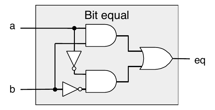
Combinational Circuit Example

Truth table
\(a\) \(b\) \(out\) 0 0 1 0 1 0 1 0 0 1 1 1
Half Adder
Adds two single bit binary numbers \(a\) and \(b\) (note: no carry input)
Truth table
\(a\) \(b\) \(c_{out}\) \(sum\) 0 0 0 0 0 1 0 1 1 0 0 1 1 1 1 0
Full adder
Adds two single bit numbers \(a\) and \(b\) (note: with a carry input)
Truth table
\(c_{in}\) \(a\) \(b\) \(c_{out}\) \(sum\) 0 0 0 0 0 0 0 1 0 1 0 1 0 0 1 0 1 1 1 0 1 0 0 0 1 1 0 1 1 0 1 1 0 1 0 1 1 1 1 1
Ripple Carry Adder
The half adder and full adder implement two bit binary addition with and without carry-in
In general, we need to add two \(n\) bit binary numbers
The ripple carry adder is \(n\) full adders cascaded together.
Example: 4 bit adder

- Note: if \(a\) is complemented and \(c_0\) set to 1, then the operation is: \(s = b - a\)
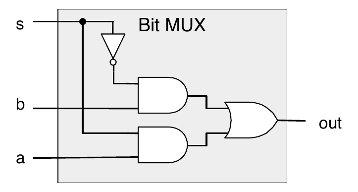
Bit-Level Multiplexor
A bit-level multiplexor has data signals \(a\) and \(b\) and a control signal \(c\) outputs \(a\) or \(b\) depending on \(c\)
Truth table
\(a\) \(b\) \(c\) out 0 0 0 0 (b) 0 0 1 0 (a) 0 1 0 1 (b) 0 1 1 0 (a) 1 0 0 0 (b) 1 0 1 1 (a) 1 1 0 1 (b) 1 1 1 1 (a)
Bit-Level Multiplexor

Arithmetic Logic Unit
- Combinational logic – a more complex version of a multiplexor
- Control signal selects function computed
Also computes condition codes
Example: four function ALU

Memory Elements
- Sequential logic has a memory
- A memory stores data
- The snapshot of the memory is called the state
- A one bit memory is called bistable, that is, it has two internal states
- Flip-flops and latches are implementations of bistables
RS Latch
An RS latch is a memory element with two inputs: reset (\(R\)) and set (\(S\)), and two outputs: \(Q\) and \(\overline{Q}\)
\(S\) \(R\) \(Q'\) \(\overline{Q'}\) comment 0 0 \(Q\) \(\overline{Q}\) hold 0 1 0 1 reset 1 0 1 0 set 1 1 0 0 illegal
where \(Q'\) is the next state and \(Q\) is the current state.
RS Latch
RS Latch State Transition Table
A state transition table is a way of viewing the operation of an RS latch.
\(Q\) \(S\) \(R\) \(Q'\) comment 0 0 0 0 hold 0 0 1 0 reset 0 1 0 1 set 0 1 1 0 illegal 1 0 0 1 hold 1 0 1 0 reset 1 1 0 1 set 1 1 1 0 illegal
Clocks and Synchronous Circuits
The RS latch output state changes occur directly in response to changes in the inputs. This is called asynchronous operation.
- Most sequential circuits employ synchronous operation.
- The output is constrained to change only at a time specified by a global enabling signal
- This signal is generally called the system clock
The clock is typically a square wave signal at a particular frequency that imposes order on the state changes.
Gated RS Latch
- The RS latch can be modified to only change state when a valid enable signal (such as from the system clock) is present.
Registers
- Store a word of data
- Different from program registers seen in assembly code
- Collection of edge-triggered latches (one for every bit in word)
- Loads input on rising edge of clock
Register Operation
- Stores data bits
- Generally acts as a barrier between input and output
- As clock rises, loads input

State Machine Example
- Accumulator circuit
- Load or accumulate on each cycle

Random-Access Memory
- Stores multiple words of memory
- Address input specifies which word to read or write
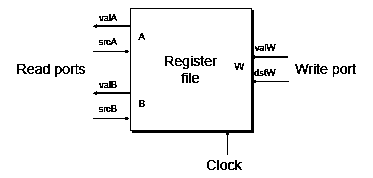
- Register file
- Holds values of program registers

Register File Timing
- Reading
- Like combinational logic
- Output generated based on input address (after some delay)
- Writing
- Like register
- Update only as clock rises
Summary
- Computation
- Performed by combinational logic
- Computes Boolean functions
- Continuously reacts to input changes
- Storage
- Registers
- Hold single words
- Loaded as clock rises
- Random-access memories
- Hold multiple words
- Can have multiple read or write ports
- Read a word when address input changes
- Write word as clock rises
- Registers


