Logic Design
CSC 235 - Computer Organization
Outline
- Introduction to binary logic gates
- Truth table construction
- Logic functions and their simplifications
- Laws of binary logic
Overview of Logic Design
- Fundamental Hardware Requirements
- Communication (how to get values from one place to another)
- Computation
- Storage
- Bits
- Everything expressed in terms of values 0 and 1
- Communication: low or high voltage on wire
- Computation: compute with Boolean functions
- Storage: store bits of information
Digital Signals
- Use voltage thresholds to extract discrete values from continuous signal.
- Simplest version: 1-bit signal
- Either high range (1) or low range (0)
- With guard range between them
- Not strongly affected by noise or low quality circuit elements
- Can make circuits simple, small and fast
Semiconductors to Computers
- Increasing levels of complexity
- Transistors built from semiconductors
- Logic gates built from transistors
- Logic functions built from gates
- Flip-flops built from logic
- Counters and sequencers from flip-flops
- Microprocessors from sequencers
- Computers from microprocessors
Semiconductors to Computers
- Increasing levels of Abstraction
- Physics
- Transistors
- Gates (this lecture)
- Logic (this lecture)
- Microprogramming
- Assembler
- Programming languages
- Applications
Logic Gates
- Basic logic circuits with one or more inputs and one output are called gates
- Gates are used as the building blocks in the design of more complex digital logic circuits.
Representing Logic Functions
- There are several ways of representing logic functions:
- Symbols to represent the gates
- Truth tables
- Boolean algebra
NOT Gate
![]()
Truth table
Boolean algebra
\[y = \overline{a}\]
AND Gate
![]()
Truth table
Boolean algebra
\[y = a \cdot b\]
OR Gate
![]()
Truth table
Boolean algebra
\[y = a + b\]
XOR Gate
![]()
Truth table
Boolean algebra
\[y = a \oplus b\]
NOT AND (NAND) Gate
![]()
NOT OR (NOR) Gate
![]()
Truth table
Boolean algebra
\[y = \overline{a + b}\]
Boolean Algebra Properties
- Commutation
- \(a + b = b + a\)
- \(a \cdot b = b \cdot a\)
- Association
- \((a + b) + c = a + (b + c)\)
- \((a \cdot b) \cdot c = a \cdot (b \cdot c)\)
- Distribution
- \(a \cdot (b + c) = (a \cdot b) + (a \cdot c)\)
- \(a + (b \cdot c) = (a+b) \cdot (a+c)\)
- Absorption
- \(a + (a \cdot c) = a\)
- \(a \cdot (a+c) = a\)
DeMorgan’s in Gates
- The function \(f = a \cdot b + c \cdot d\) can be implemented with AND and OR gates
![]()
DeMorgan’s in Gates
- Two consecutive NOT gates cancel out.
![]()
DeMorgan’s in Gates
- The function \(f = a \cdot b + c \cdot d\) can be simplified to use only NAND gates.
![]()
Logic Minimisation
- Any Boolean function can be implemented directly using combinational logic
- Simplifying the Boolean function will reduce the number of gates required to implement the function
- Logic minimization techniques:
- Algebraic manipulation
- Karnaugh (K) mapping (visual approach)
- Tabular approaches (for example Quine-McCluskey)
- Karnaugh mapping is usually preferred for up to about 5 variables
Maxterms
A maxterm of \(n\) Boolean variables is the disjunction of all the variables either in complemented or uncomplemented form.
Example (referring to the truth table for \(f\))
\[\begin{align*}
\overline{f} &= x \cdot \overline{y} \cdot \overline{z} + x \cdot \overline{y} \cdot z + z \cdot y \cdot \overline{z}\\
f &= (\overline{x} + y + z) \cdot (\overline{x} + y + \overline{z}) \cdot (\overline{x} + \overline{y} + z)
\end{align*}\]
- The maxterms of \(f\) are effectively the minterms of \(\overline{f}\) with each variable complemented.
Logic Simplification
- Boolean algebra can be used to simplify logical expressions.
- Note: the DNF and CNF are not simplified
- There is a technique called Karnaugh mapping that is sometimes easier (for humans to do)
POS Simplification
- Note that the previous examples yielded simplified expressions in the SOP form
- Suitable for implementations using AND followed by OR gates, or only NAND gates
- Sometimes we may wish to get a simplified expression in POS form
- Suitable for implementations using OR followed by AND gates, or only NOR gates
- To do this we group zeros in the map, then apply DeMorgan’s and complement
POS Example
Simplify \(f = \overline{a} \cdot b + b \cdot \overline{c} \cdot \overline{d}\) into POS form
![]()
Simplified: \(\overline{f} = \overline{b} + a \cdot c + a \cdot d\)
Applying DeMorgan’s: \(f = b \cdot ( \overline{a} + \overline{c}) \cdot (\overline{a} + \overline{d})\)
Don’t Care Conditions
Sometimes we do not care about the output value of a combinational logic circuit, for example, if certain input combinations can never occur.
These are called don’t care conditions
In a simplification they may be treated as 0 or 1 depending on which gives the simplest result
Don’t Care Conditions Example
Simplify the function \(f = \overline{a} \cdot \overline{b} \cdot d + \overline{a} \cdot c \cdot d + a \cdot c \cdot d\) with don’t care conditions \(\overline{a} \cdot \overline{b} \cdot \overline{c} \cdot \overline{d}\), \(\overline{a} \cdot \overline{b} \cdot c \cdot \overline{d}\), \(\overline{a} \cdot b \cdot \overline{c} \cdot d\)
![]()
Simplified: \(f = \overline{a} \cdot \overline{b} + c \cdot d\) or \(f = \overline{a} \cdot d + c \cdot d\)
K-map Definitions
Cover - a term is said to cover a minterm if that minterm is part of that term
Prime implicant - a term that cannot be further combined
Essential term - a prime implicant that covers a minterm that no other prime implicant covers
Covering set - a minimum set of prime implicants which includes all essential terms plus any other prime implicants required to cover all minterms
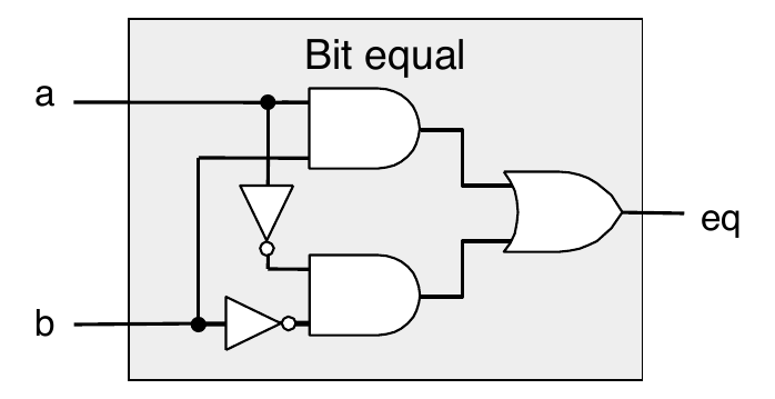
Combinational Circuit Example
![]()
Ripple Carry Adder
The half adder and full adder implement two bit binary addition with and without carry-in
In general, we need to add two \(n\) bit binary numbers
The ripple carry adder is \(n\) full adders cascaded together.
Example: 4 bit adder
![]()
- Note: if \(a\) is complemented and \(c_0\) set to 1, then the operation is: \(s = b - a\)
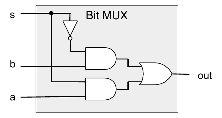
Bit-Level Multiplexor
![]()
Memory Elements
- Sequential logic has a memory
- A memory stores data
- The snapshot of the memory is called the state
- A one bit memory is called bistable, that is, it has two internal states
- Flip-flops and latches are implementations of bistables
RS Latch
where \(Q'\) is the next state and \(Q\) is the current state.
RS Latch
![]()
RS Latch State Transition Table
Clocks and Synchronous Circuits
The RS latch output state changes occur directly in response to changes in the inputs. This is called asynchronous operation.
- Most sequential circuits employ synchronous operation.
- The output is constrained to change only at a time specified by a global enabling signal
- This signal is generally called the system clock
The clock is typically a square wave signal at a particular frequency that imposes order on the state changes.
Gated RS Latch
- The RS latch can be modified to only change state when a valid enable signal (such as from the system clock) is present.
![]()
Registers
- Store a word of data
- Different from program registers seen in assembly code
- Collection of edge-triggered latches (one for every bit in word)
- Loads input on rising edge of clock
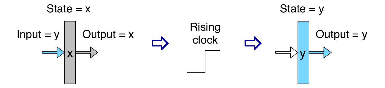
Register Operation
- Stores data bits
- Generally acts as a barrier between input and output
- As clock rises, loads input
![]()
State Machine Example
- Accumulator circuit
- Load or accumulate on each cycle
![]()
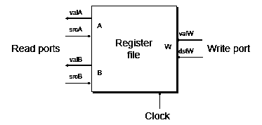
Random-Access Memory
- Stores multiple words of memory
- Address input specifies which word to read or write
- Register file
- Holds values of program registers
![]()
Register File Timing
- Reading
- Like combinational logic
- Output generated based on input address (after some delay)
- Writing
- Like register
- Update only as clock rises
Summary
- Computation
- Performed by combinational logic
- Computes Boolean functions
- Continuously reacts to input changes
- Storage
- Registers
- Hold single words
- Loaded as clock rises
- Random-access memories
- Hold multiple words
- Can have multiple read or write ports
- Read a word when address input changes
- Write word as clock rises