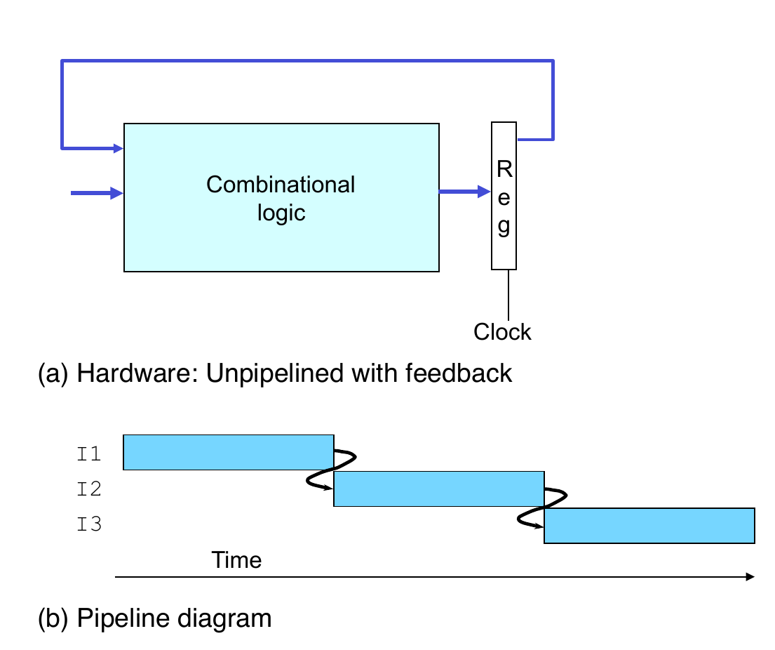
Result from one instruction used as operand for another
Read-after-write (RAW) dependency
Common in actual programs
Must make sure our pipeline handles these properly
get correct results
minimize performance impact
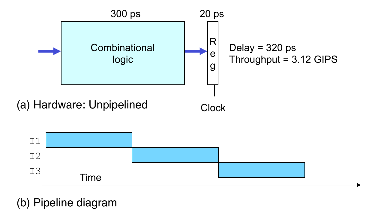
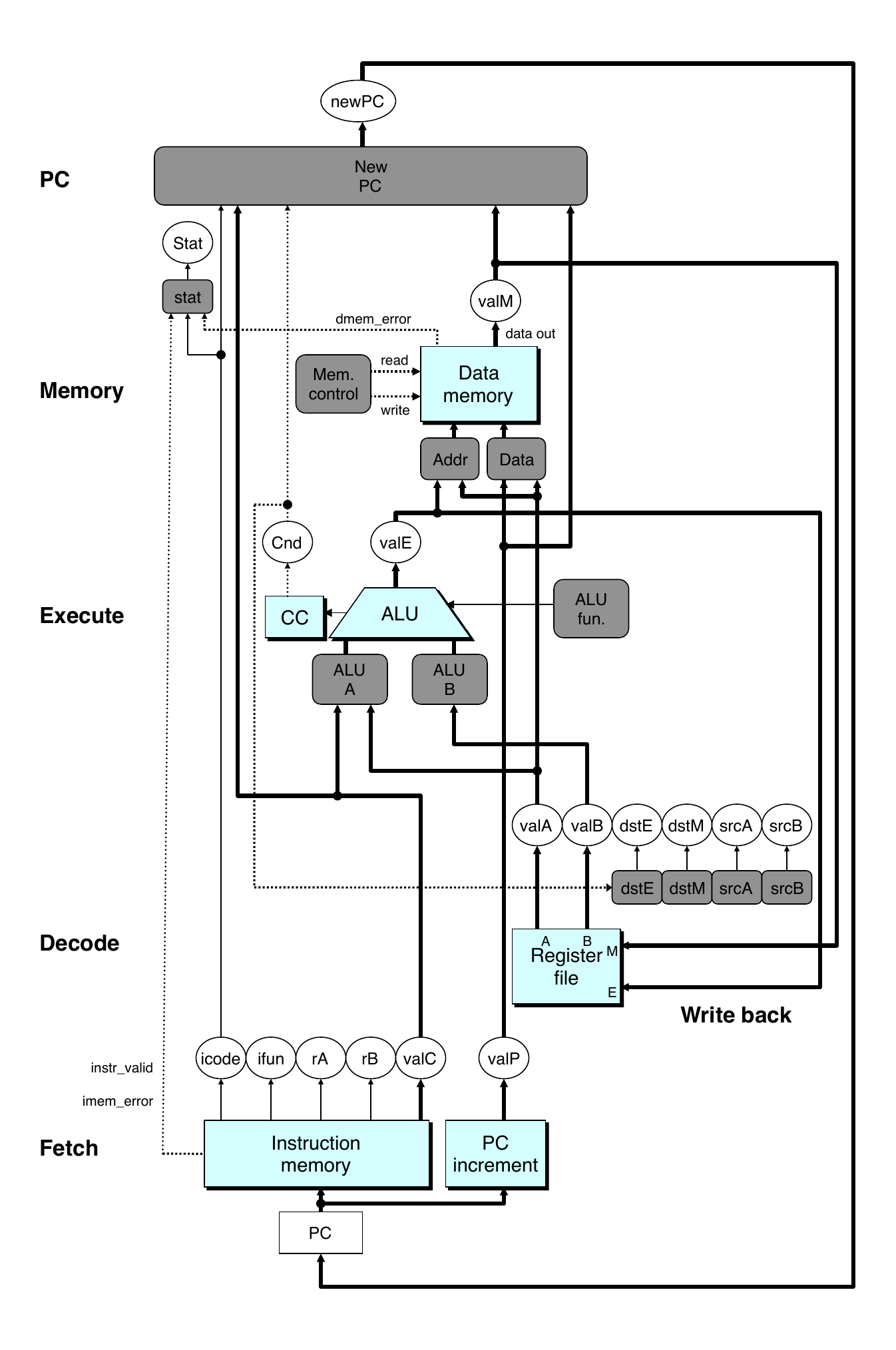
Sequential Hardware
Sequential Hardware
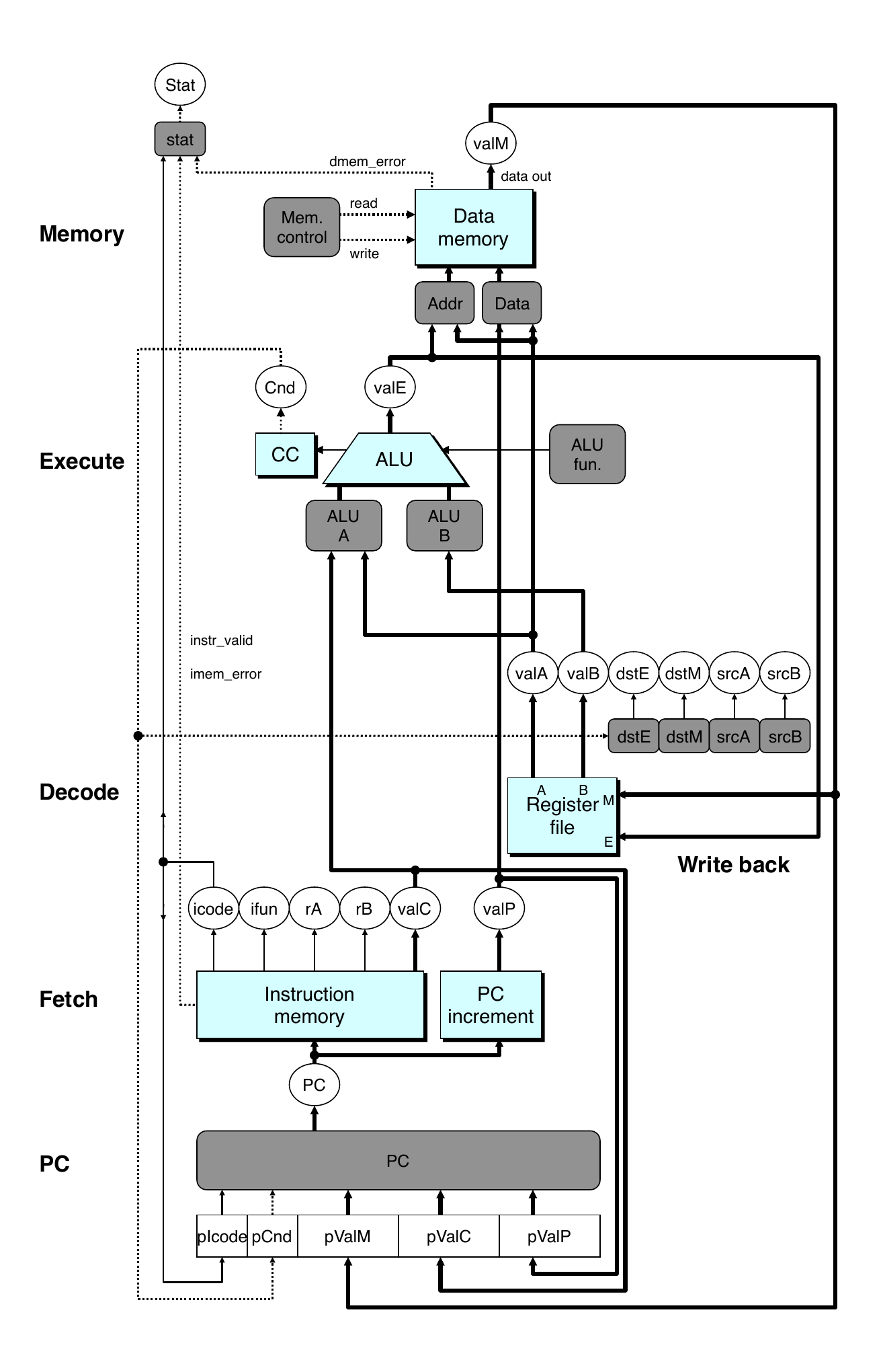
Modified Sequential Hardware
Modified Sequential Hardware
Modified Sequential Hardware
Reorder PC stage to be at the beginning
PC stage
Task is to select PC for current instruction
Based on results computed by previous instruction
Processor state
PC is no longer stored in register
PC can be determined based on other stored information
Pipeline Stages
Fetch
Select current PC
Read instruction
Compute incremented PC
Decode
Read program registers
Execute
Operate ALU
Memory
Read or write data memory
Write Back
Update register file
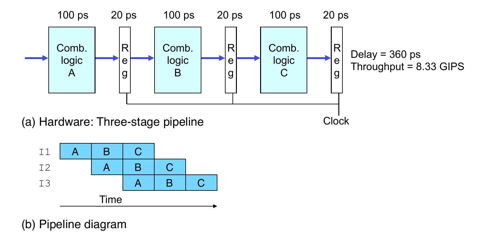
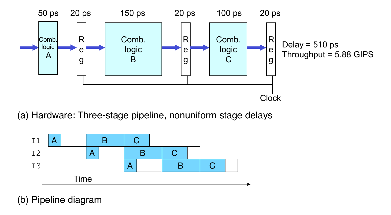
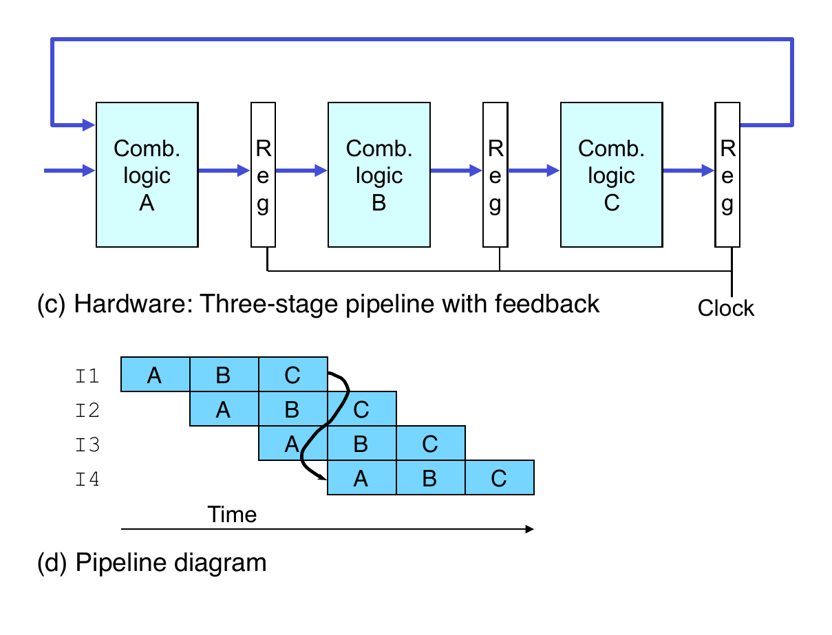
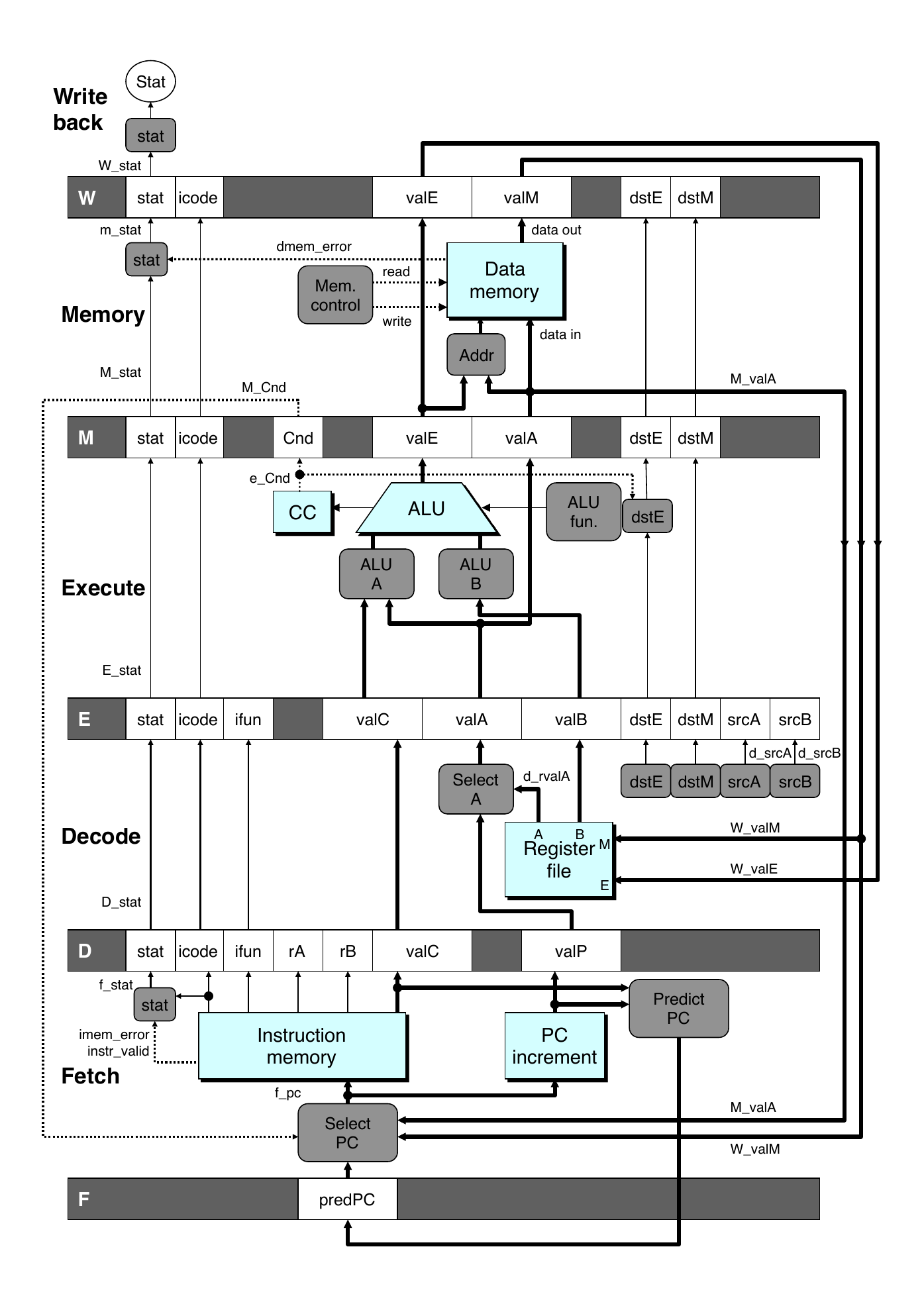
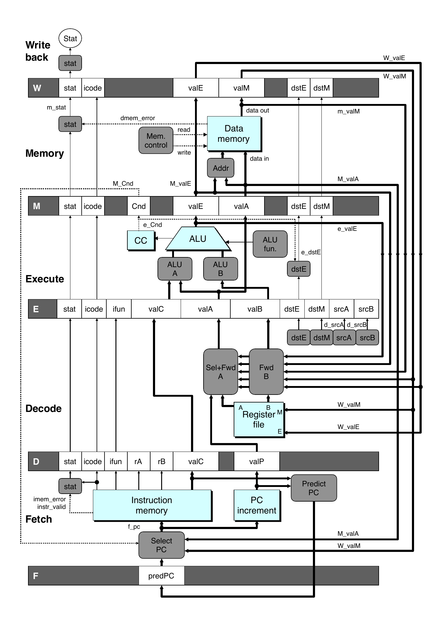
Pipelined Hardware
Pipelined Hardware
Pipelined Hardware
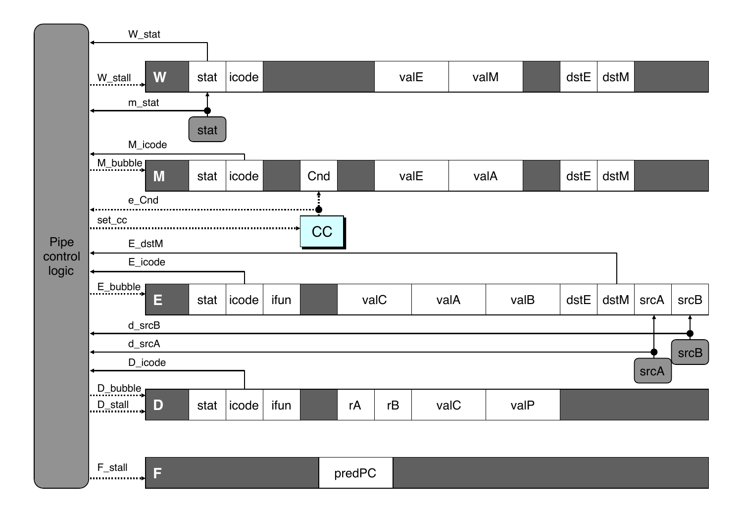
Pipeline registers hold intermediate values from instruction execution
Forward Paths
Values passed from one stage to the next
Cannot jump past stages
For example, valC passes through decode
Signal naming conventions
S_Field: value of field held in stage S pipeline register
s_Field: value of field computed in stage S
Feedback Paths
Predicted PC
Guess value of next PC
Branch information
Jump taken/not taken
Fall-through or target address
Return point
Read from memory
Register updates
To register file write ports
Predicting the PC
Start fetch of new instruction after current one has completed fetch stage
Not enough time to reliably determine next instruction
Guess which instruction will follow
Recover if prediction was incorrect
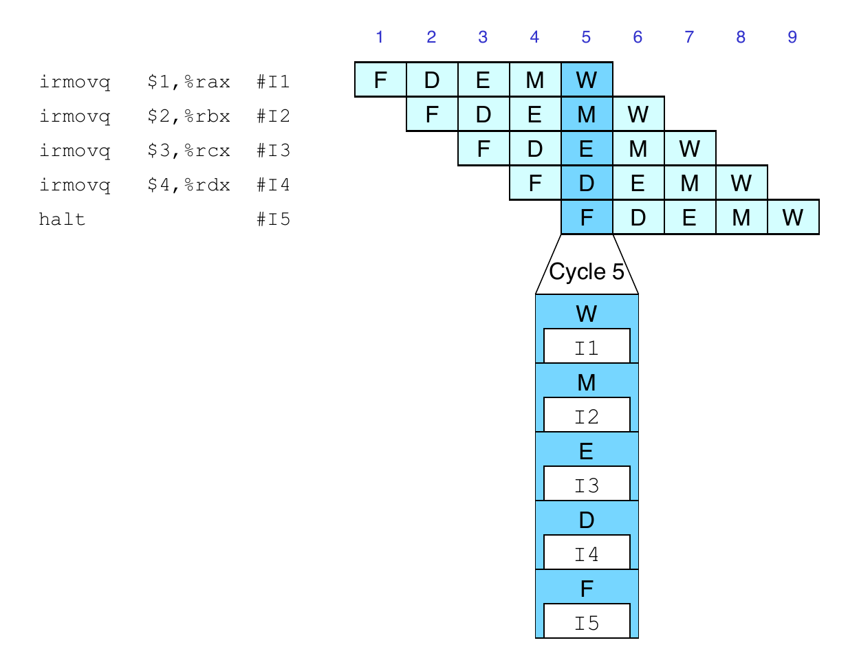
Pipeline Demonstration
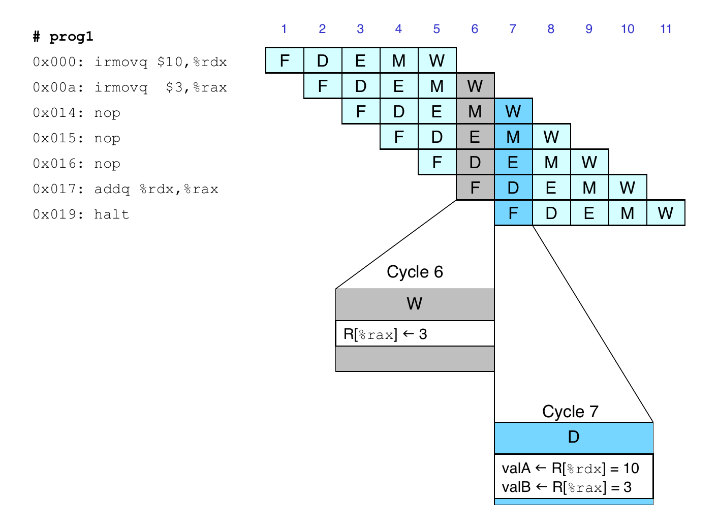
Data Dependencies: 3 nop Instructions
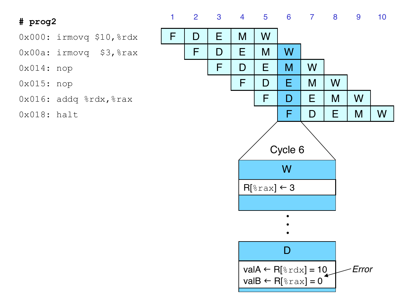
Data Dependencies: 2 nop Instructions
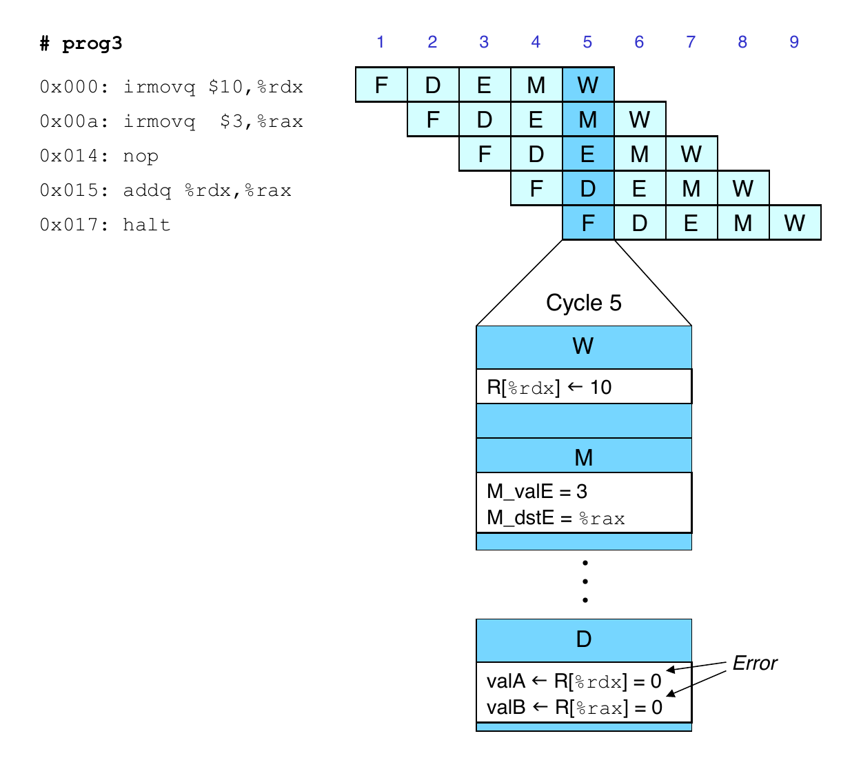
Data Dependencies: 1 nop Instruction
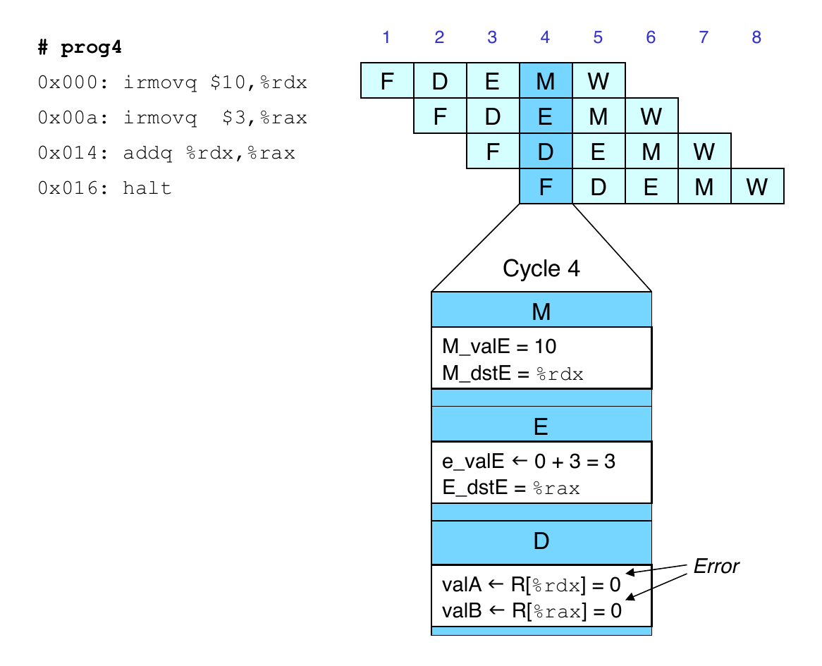
Data Dependencies: No nop Instruction
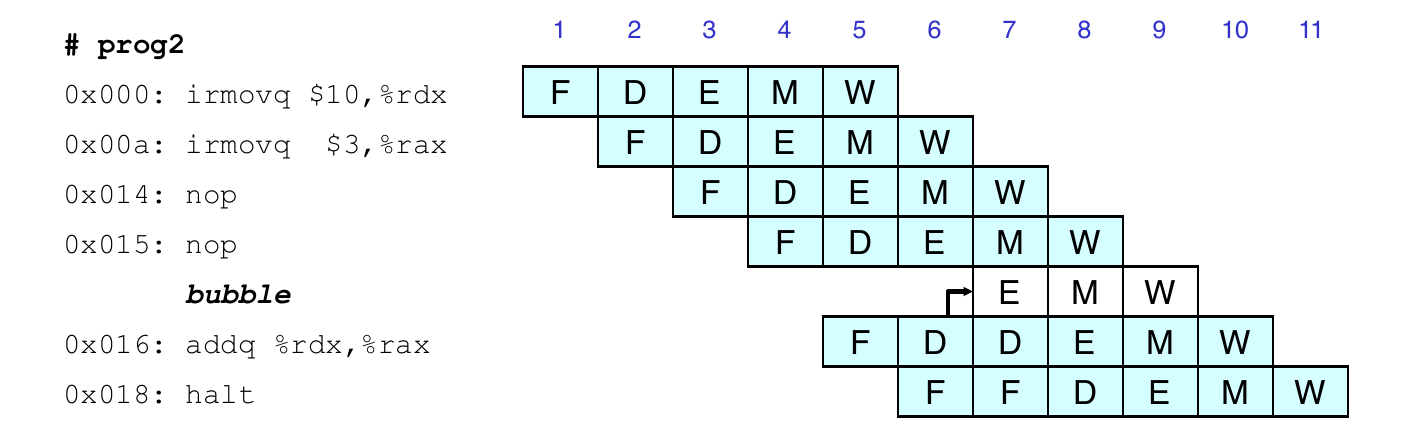
Stalling for Data Dependencies
If instruction follows too closely after one that writes to register, then slow it down
Hold instruction in decode
Dynamically inject nop into execute stage
Stall Condition
Source Registers
srcA and srcB of current instruction in decode stage
Destination Registers
dstE and dstM fields
Instructions in execute memory, and write back stages
Special case
Do not stall for register ID 15 (0xF)
Indicates absence of register operand
Or failed conditional move
Stall Example
What Happens When Stalling
Stalling instruction held back in decode stage
Following instruction stays in fetch stage
Bubbles injected into execute stage
Like dynamically generated nops
Move through later stages
Implementing Stalling
Pipeline Control
Combinational logic detects stall condition
Sets mode signals for how pipeline registers should update
Data Forwarding
Basic Pipeline
Register is not written until completion of write back stage
Source operands read from register file in decode stage
Needs to be in register file at start of stage
Observation
Value generated in execute or memory stage
Trick
Pass value directly from generating instruction to decode stage
Needs to available at end of decode stage
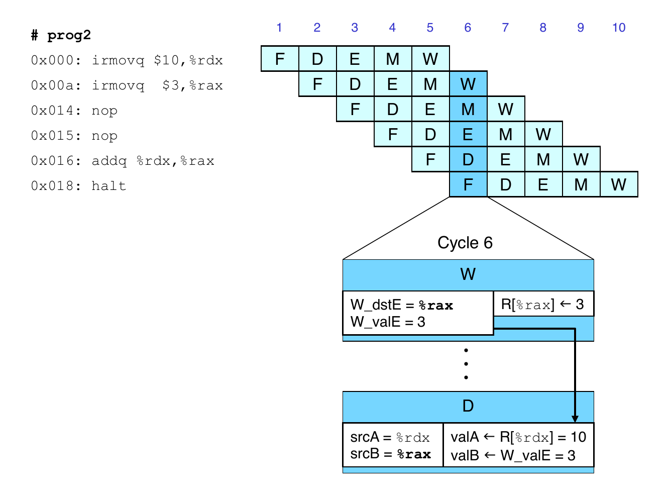
Data Forwarding Example
irmovq in write back stage
Destination value in W pipeline register
Forward as valB for decode stage
Data Forwarding Example
Register %rdx
Generated by ALU during previous cycle
Forwarded from memory as valA
Register %rax
Generated by ALU
Forwarded from execute as valB
Forwarding Priority
Multiple forwarding choices
Which one should have priority
Match serial semantics
Use matching value from earliest pipeline stage
Implementing Forwarding
Add additional feedback paths from E, M, and W pipeline registers into decode stage
Create logic blocks to select from multiple sources for valA and valB in decode stage
Implementing Forwarding
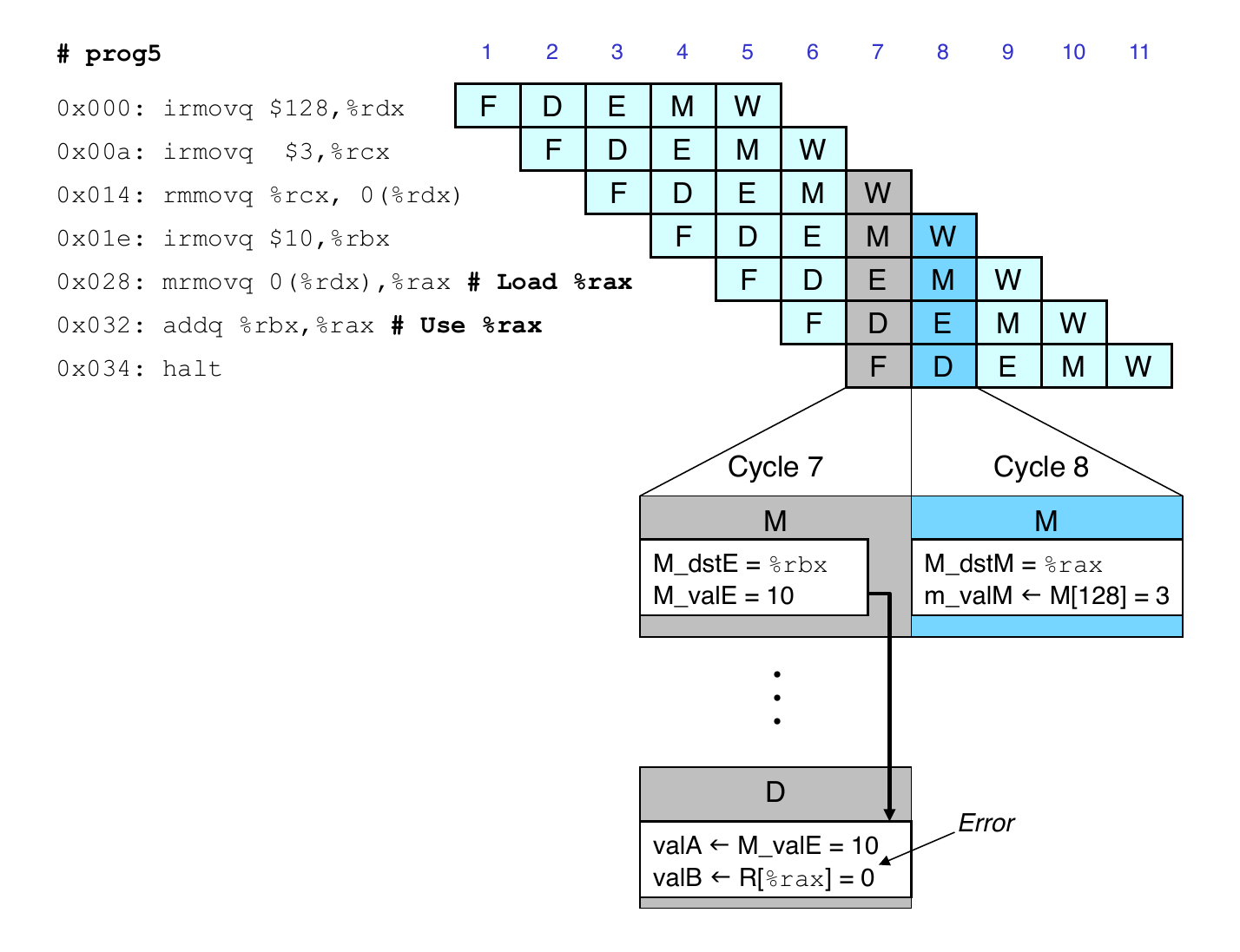
Limitation of Forwarding
Load-use dependency
Value needed by end of decode cycle 7
Value read from memory in memory stage of cycle 8
Avoiding Load/Use Hazard
Stall using instruction for one cycle
Can then pick up loaded value by forwarding from memory stage
Load/Use Hazard Implementation
Detecting load/use hazard
If E_icode is imrmovq or popq and E_dst_M is d_srcA or d_srcB
Control for load/use hazard
Stall instructions in fetch and decode stages
Inject bubble into execute stage
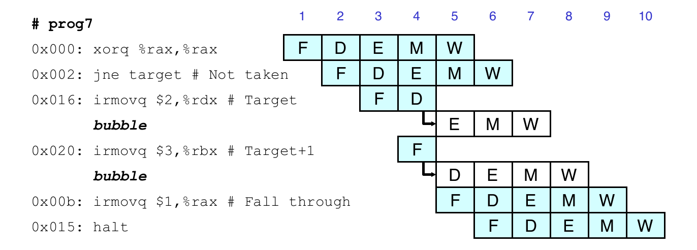
Branch Misprediction Example
0x000:    xorq %rax, %rax
0x002:    jne t             # not taken
0x00b:    irmovq $1, %rax   # fall through
0x015:    nop
0x016:    nop
0x017:    nop
0x018:    halt
0x019: t: irmovq $3, %rdx   # target
0x023:    irmovq $4, %rcx   # should not execute
0x02d:    irmovq $5, %rdx   # should not execute
Should only execute first 8 instructions
Handling Branch Misprediction
Predict branch as taken
Fetch 2 instructions at target
Cancel when mispredicted
Detect branch not-taken in execute stage
On following cycle, replace instructions in execute and decode bubbles
No side effects have occurred yet
Branch Misprediction Implementation
Detecting branch misprediction
If E_icode is jXX and not e_Cnd
Control for branch misprediction
Inject bubble into decode and execute stages
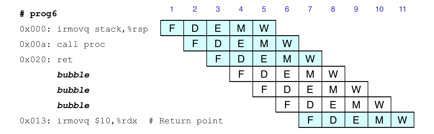
Return Example
0x000:    irmovq Stack, %rsp   # intialize stack pointer
0x00a:    call p               # procedure call
0x013:    irmovq $5, %rsi      # return point
0x01d:    halt
0x020: .pos 0x20
0x020: p: irmovq $-1, %rdi     # procedure
0x02a:    ret
0x02b:    irmovq $1, %rax      # should not be executed
0x035:    irmovq $2, %rax      # should not be executed
0x03f:    irmovq $3, %rax      # should not be executed
0x049:    irmovq $4, %rax      # should not be executed
0x100: .pos 0x100
0x100: Stack:                  # Stack pointer
Correct Return Example
As ret passes through pipeline, stall at fetch stage
While in decode, execute, and memory stage
Inject bubble into decode stage
Release stall write back stage is reached
Return Implementation
Detecting branch misprediction
If D_icode or E_icode or M_icode is ret
Control for branch misprediction
Stall fetch stage
Inject bubble into decode stage
Special Control Cases
Detection
Condition
Trigger
Processing ret
IRET in {C_icode, E_icode, M_icode}
Load/use hazard
E_icode in {IMRMOVQ, IPOPQ} && E_dstM in {d_srcA, d_srcB}
Mispredicted branch
E_icode = IJXX & !e_Cnd
Action (on next cycle)
Condition
Fetch
Decode
Execute
Memory
Write back
Processing ret
stall
bubble
normal
normal
normal
Load/use hazard
stall
stall
bubble
normal
normal
Mispredicted branch
normal
bubble
bubble
normal
normal
Control Combinations
Special cases that can arise on same clock cycle
Combination A
Not-taken branch
ret instruction
Combination B
Instruction that reads from memory to rsp
Followed by ret instruction
Handling Control Combinations
Combination A
Should handle as mispredicted branch
Stall fetch pipeline register
PC selection logic will be using M_valM
Combination B
Would attempt to bubble and stall pipeline register D
Signaled by processor as pipeline error
Load/use hazard should get priority
ret instruction should be held in decode stage for additional cycle
Pipeline Summary
Data Hazards
Most handled by forwarding
Load/use hazard requires one cycle stall
Control Hazards
Cancel instructions when mispredicted branch is detected
Two clock cycles wasted
Stall fetch stage while ret passes through pipeline